|
Trestles – RGS StyleWooden Trestle Constructionon the Rio Grande Southern Railroadby Bob Hyman
Part 1 – Prototype TrestlesIntroductionWhen completed, the Rio Grande Southern Railroad had 142 bridges scattered along its 162 miles of track. Almost all of the original bridges were rebuilt or replaced at one time or another. The early Howe truss bridges were replaced with simple open deck trestles, and many of the smaller bridges were replaced with earthen fills and culverts. By the end of operations, 111 bridges were left on the railroad; virtually none were original. The reasons for replacing a bridge were many, but for the most part, the arrival of heavier motive power or damage caused by weather and high water resulted in replacement.
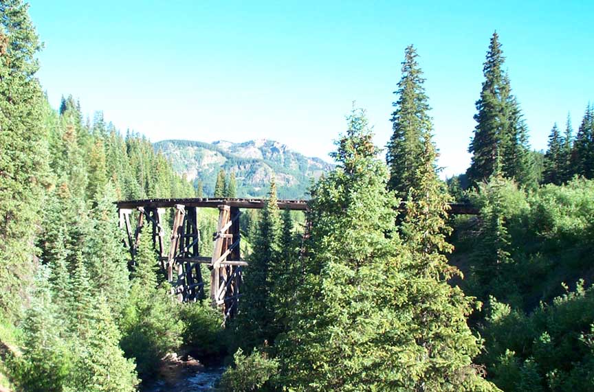
Figure 1 – Bridge 51-A (Lake Fork Trestle) At first glance, most of the trestles appear to be similar. However, a closer look shows that all differ in detail. The RGS built its bridges following accepted and proven engineering practices, but did not adhere to strict standardization. Thus, all of the bridges look similar in overall design, but still have individual characteristics. Some detail differences in the bridges occurred due to unusual circumstances in placement or geography. Other differences were due to the availability of materials and the financial status of the line when repairs were made. Changes also occurred depending on what practices were in favor when the bridges were repaired. Thus, over time, all of the bridges slowly changed. This handout details some of the basic design standards and building techniques that the trestles adhered to, no matter their differences in detail. It explores some of the more obvious differences, particularly on the large timber trestles on the high line over Lizard Head Pass between Vance Junction and Rico. In addition to explaining prototype construction methods, techniques are presented for building accurate scale models of these trestles. Basic Trestle ComponentsA trestle is composed of an open, braced wooden framework that supports the railroad above ground level. It consists of a series of identical (or nearly so) vertical supports holding up a succession of short spans. All wood portions of a trestle are designed to be in compression and never in tension. BentsThe deck of a trestle is supported by vertical structures called bents. There are two types of bents. The pile bent has round posts, usually twelve inches in diameter, which are driven directly into the ground. The frame bent has square posts sitting on a horizontal bottom support member called a sill. The sill usually rests on a separate foundation. Both types of bents have a horizontal cap resting on top of the posts. The cap equally distributes the load from the bridge deck above to the posts below. The space between two adjacent bents is called a panel.
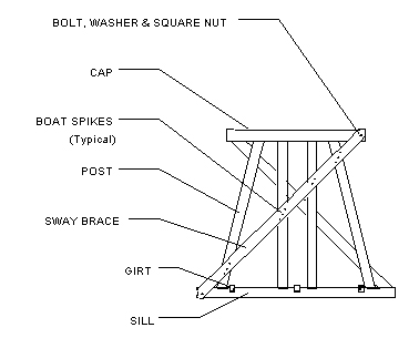
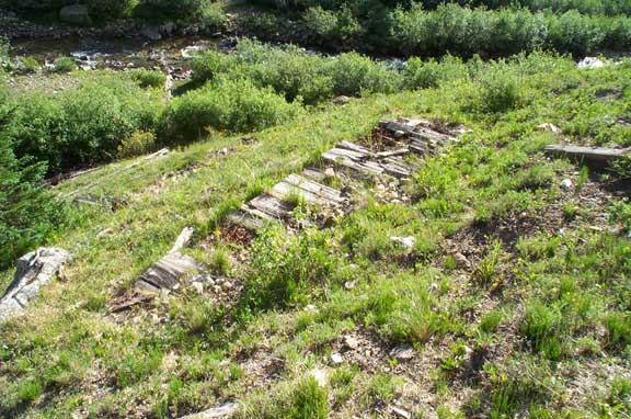
Figure 2 – Typical Bent Components There are a minimum of four posts in a bent – two (sometimes three) inner posts and two outer posts. The inner posts are usually (but not always) vertical. The outer posts are angled 2″ to 3″ per foot. This angle is called batter. Additional intermediate posts may be present in the bent between the inner and outer posts. These are also battered, either at the same angle as the outer posts, or at some lesser angle. Batter is expressed as a ratio of spread to height, e.g., 2 in 12 or 3 in 12. Pile bents were not made higher than thirty feet due to the length of available wood material (generally no longer than 60 feet). This is because each pile is a single piece, and a sizeable portion of it must be driven into the ground. Also, the round configuration is not easily adapted to the construction of tall trestles. Piles were always driven with the narrow diameter down. Frame bents were typically built from around five to a maximum of thirty feet tall, also due to the length of available posts. If a taller trestle was required, the bents were divided into stories, separated by horizontal intermediate 12″-square sills. In normal practice, the bent heights varied as necessary for the bridge to fit into the terrain. For heights under 16 to 20 feet, one story was used. For heights over this, anywhere from two to five stories would be used; the upper stories were normally the full height and the bottom one was adjusted to fit as necessary. BracingMost bents have diagonal sway bracing for reinforcement. These sway braces are lengths of 3″ x 10″ or 3″ x 12″ lumber attached to the cap, posts and sill at an angle somewhere between 30 and 60 degrees. Sway bracing typically runs from upper-right to lower-left, although many reversed examples are found. The ends of the sway braces were sometimes cut at an angle to match the ends of the caps and sills; others were left as normal perpendicular cross cuts. If the distance from corner to corner of the bent was longer than the available bracing boards, two boards would be used. The RGS bridge crews were very resourceful when it came to using whatever material was available to get the job done! Occasionally, bents have horizontal 3″ x 12″ braces on each side of the bent about halfway between the cap and the sill. These horizontal braces are called sashes. Although sash bracing is common on pile bents, it is rarely used on frame bents. Bridge 58-A, the Meadow Creek Trestle, and Bridge 51-A, the Lake Fork Trestle, are notable exceptions. To make a trestle rigid along the length, horizontal timbers called girts are placed on top of the sills or sashes, and connect each bent to the next. When extra longitudinal stiffness is required, the bents are connected with wall bracing. This bracing lies parallel to the sides of the trestle and connects the posts of adjacent bents with crossed pieces. Wall bracing is generally the same size as sway bracing. The RGS did not use wall bracing often; a notable exception is Bridge 58-A. FoundationsThe bottom sill of a frame bent is called a mud sill. It may rest on a variety of foundations. Some trestles had the mud sill attached to the tops of piles driven into the ground. Others rested on blocks of used bridge timbers, typically 8″ x 18″ x 3 feet (see Figure 3). Occasionally a mud sill would rest directly on the ground. In the later years, poured concrete was common (see Figure 4).
Figure 3 – Bridge 57-A Timber Block Foundation
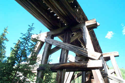
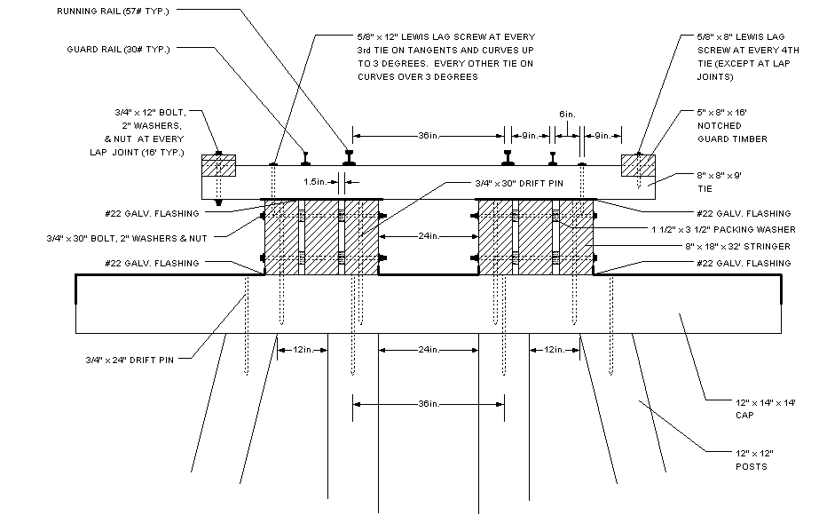
Figure 4 – Bridge 45-A Poured Concrete Foundation DeckThe deck of a trestle starts with wooden stringers set on top of the bent caps. The bents were generally placed 16 feet apart, with stringers of 8″ x 18″. If the bents needed to be farther apart, stringer size was increased to 8″ x 24″. Standard 8″ x 18″ stringers were 32 feet long and spanned two panels. Three stringers were bolted together into a single beam, leaving a 1 ½” space between the individual stringers for ventilation. Two beams were placed side-by-side, about two feet apart, on the caps. Bridge ties were laid on the stringers, and guard timbers ran the length of the deck at the tie ends. The guard timbers were usually notched to fit over the tie ends and hold them in alignment. Galvanized sheet metal was placed on the tops of the bent caps and on the tops of the stringers to protect the wood from falling cinders. Running rails, gauged at three feet, were spiked to every tie. Guard rails, when used, were generally spiked to every fourth tie. Initially, the guard rails were located inside of the running rails. Later, they were moved outside of the running rails, probably to provide clearance for blade flangers. Design and MaterialsThe drawings at the end this handout represent typical multi-story bents from curved, tangent and compound (both curved and tangent) RGS trestles. Tangent trestles were generally built with a batter, or slope, of 2 in 12 on the outer posts, while curved trestles had a batter of 3 in 12. The drawings show the height of each story. Two major styles of trestle bents were used on the RGS. One style used two vertical posts in the center and the other used three. Some trestle bents were built without vertical posts, and used 1 in 12 batter for the inner posts. Construction DetailsThe prototype photos in this handout show timber remnants from RGS trestle sites. Bridge 51-A is the only one of the large RGS trestles still standing. It was maintained for a while after abandonment by the state of Colorado, but for the most part, it exists today just as it did when the RGS ran trains over it. The dimensions of the wooden members of this bridge are consistent with normal railroad practice, and the metal hardware used to tie the bridge together is basically the same as observed in the remains of many other bridges. Construction MethodsFigure 5 shows the method generally used by the RGS to tie trestle components together. This style of construction has been observed at some of the major bridge sites on the railroad that contain enough material for examination. It is also evident in the water towers still standing.
Figure 5 – Construction Details (Typical) The cap was attached to the posts underneath it by driving a round 3/4″ diameter x 24″ long steel drift pin down through the cap and into the post. This was done for each post and for each story of every bent. The deck beams were attached to the caps by driving a round 3/4″ diameter x 30″ long steel drift pin down through the stringers and into the cap.
Figure 6 – Stringer Connection Details (Tangent Trestle) The individual stringers making up each beam were typically 32 feet long and spanned two panels. The ends of the stringers were staggered as shown in Figures 6 and 7. The stringers were bolted together with 3/4″ diameter x 30″ long bolts, 2″ washers and nuts. On a tangent trestle, the stringers making up the beams were parallel to each other (see Figure 6). 1 1/2″ x 3 1/2″ packing washers were placed on the bolts between the stringers to maintain spacing. If the trestle was on a curve, the stringers making up each beam were not parallel to each other, but were angled as shown in Figure 7.
Figure 7 – Stringer Arrangement (Curved Trestle) The ties were typically attached to the beams with 5/8″ diameter x 12″ long Lewis lag screws. The screws were placed in every third tie on tangents and curves up to three degrees, and in every other tie on curves over three degrees.
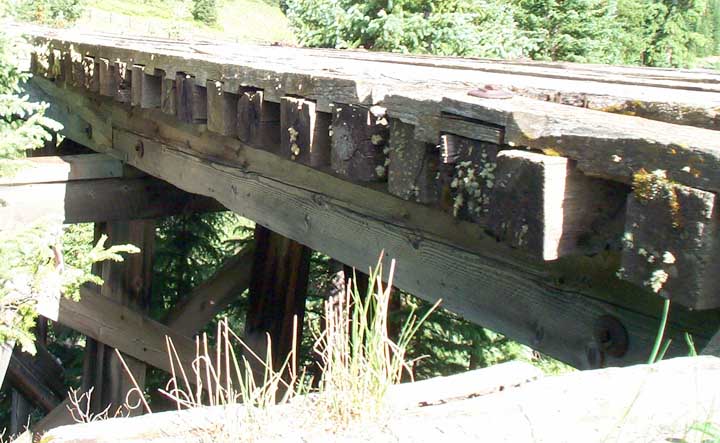
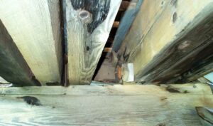
Figure 8 – Guard Timber Details The notched guard timbers were typically screwed to every fourth tie with 5/8″ diameter x 8″ long Lewis lag screws, except at lap joints where two guard timbers were spliced together. At lap joints, the two guard timbers were attached to the tie with a 3/4″ diameter x 12″ bolt, 2″ washer and nut. Figure 9 shows deck details of Bridge 51-A.
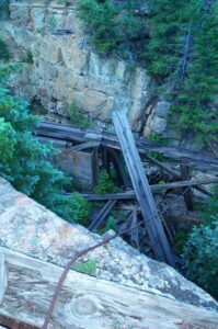
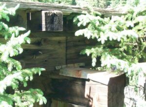
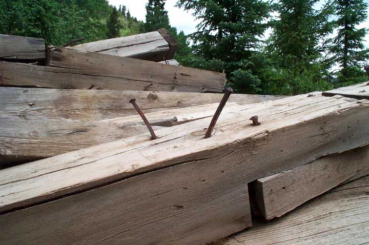
Figure 9 – Deck Detail Photos Anywhere from one to three small bridge nails (8″ or 9″ long with 3/8″ shaft) were used to attach the sway braces to the posts. These are often called boat spikes. Boat spikes are found with both circular and square cross-sections. The sway braces usually ran from the lower left to upper right. This unit or story was often assembled off to the side and then moved into position on the bridge. Figure 10 shows bridge nails in a sill of Bridge 44-A (Butterfly Trestle). Note how sill was notched at lap joint. Extended nails show where a post was toe-nailed to the sill.
Figure 10 – Bridge Nail Photo Each story was attached to the one below by toe-nailing several full sized bridge nails through the post and into the cap of the story underneath. In the bottom story, the mud sill would probably be attached before the story was moved into place. As each story was positioned and attached to the story below, girts were added between the bents to stabilize them. When finished these bridges were strong and stable. The bridge at Ames, (43A), which was built in a very precarious location, stood for almost thirty years after abandonment with no maintenance whatsoever. Materials Used
Trestle Construction and Upgrade Highlights
|