Planning a Tapered Steam Locomotive Boiler
If you ever find yourself deciding to build a steam locomotive from scratch, one of the challenges you might face is making a boiler shell for it. Of course there are shortcuts if, for example, the locomotive you are modeling can be kitbashed from an existing model, or it has a straight boiler that scales out close to a standard pipe size. The ready-made options can be pretty limited though, and if the engine you’re building has a pronounced taper to the boiler, sometimes you really have no other choice but to roll your own.
Locomotive boilers are made up of sections, called courses, that can be straight or tapered. Laying out a straight boiler course on a flat sheet is pretty simple – it’s just a rectangle where one dimension is the length of the boiler course, and the other is the circumference (diameter × 3.14). Tapered courses can be tricky though. For these, you will need to lay out a curved shape on the flat that, when rolled, becomes a truncated cone. Luckily, there are tools out there that take the hard work out of figuring out the geometry, and will generate a printable template in the correct shape.
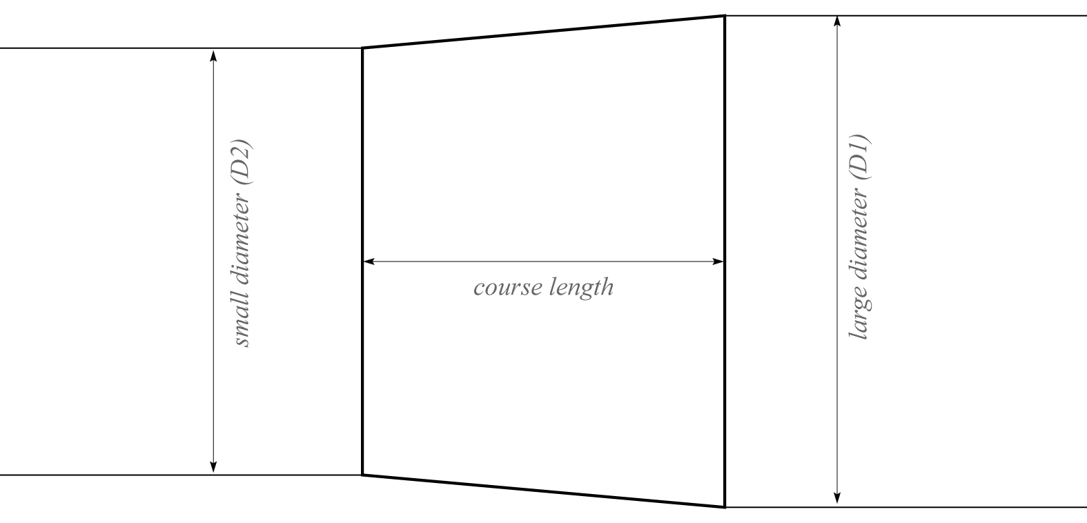
Some locomotive boilers had a very shallow taper that was equal all around, so that the boiler courses were concentric. For these, the boiler course is a relatively straightforward cone shape. There are some easy-to-use free cone template generators available online, where you feed it the larger diameter, the smaller diameter, and the length between them, and it will render a printable template for your cone. Here are links to a couple of them.
- https://www.blocklayer.com/cone-patternseng.aspx
- http://www.templatemaker.nl/index.php?template=cone&lang=en
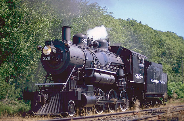
Other locomotives (including Northern Pacific 328, the subject of my scratchbuilding project) had a pronounced “wagon top”, where the top of the boiler sloped sharply upwards from one course to the next, but the bottom remained level. For these, you will need to create what is known as an “eccentric cone”, where the centers of the two faces are vertically offset from each other.
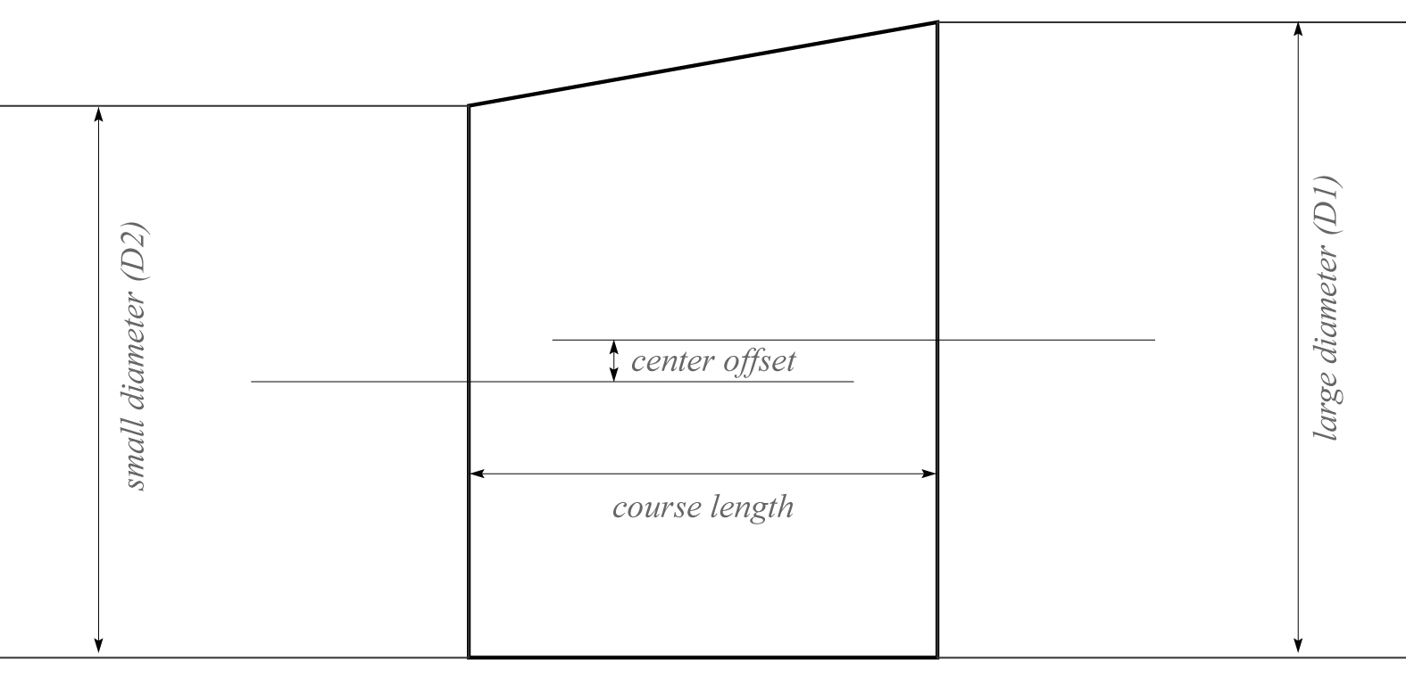
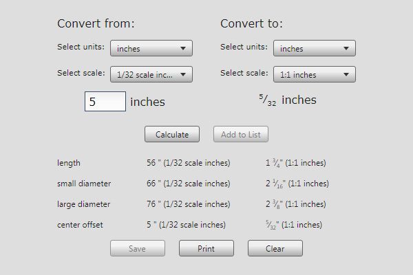
For my example, the tapered second course of the full-sized locomotive is 56″ long, the diameter where it meets the first course is 66″, and the diameter where it meets the third course is 76″. The center of the smaller diameter is offset from the center of the larger diameter by 5″ (half of the difference between the two diameters). Converting these full-sized dimensions to model dimensions using the handy NHGRS Scale Conversion Calculator (or simply dividing by 32, since I’m working in 1:32 scale), we get 1.75″, 2.0625″, 2.375″, and 0.15625″.
What would be really nice is a tool where you could input the length, the two diameters, and the center offset to generate an eccentric cone template. Unfortunately, that doesn’t seem to be an option with the free online cone generators I found. With a little digging around online however, I was able to find this handy tool, which is free to download on a 21-day trial basis (which should be more than enough time for our purposes anyway), or can be purchased for a pretty reasonable $39.00:
Like the free online generators, the Cone Layout tool takes the diameters of the two cone faces and the distance between them. It doesn’t give us a field to define the center offset, but what it does give us is the ability to change the face angles. That will give us what we need, but to get there we have to approach the problem a little bit differently.
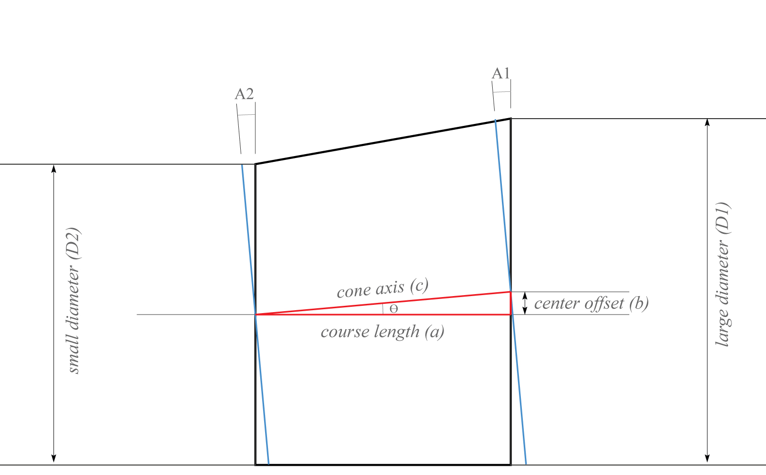
First of all, our “length” is no longer the horizontal length of the boiler course, it’s the length of the cone axis, the diagonal line between the centers of the two cone faces. Time to blow the cobwebs off the old high school geometry! The diagonal axis is the hypotenuse (c) of the right triangle highlighted in red in fig. 3, formed by the length of the boiler course on one leg (a) and the center offset on the other leg (b). The formula for calculating its length (with numbers plugged in from my example) is:
![]()
The other thing we need to calculate is the angles of the two cone faces. The tool allows us to change them independently, but since they’ll be parallel in our application, the angle will be the same for both of them. A value of 0° means the face is perpendicular to the axis (represented by the blue lines in fig.3), but our axis is diagonal and we want the faces to be vertical, so we have to calculate the angle (ϴ) of the axis off the horizontal, and use that value for the angle of the two cone faces (A1 and A2). To do that, we have to go back to our right triangle and do a little trigonometry. If you’re like me and have gotten a bit rusty with this stuff, here’s a handy cheat…
Using the course length (1.75) for the base and center offset (0.15625) for the height, we get an angle ϴ of 5.1021652523582. Now we’re ready to plug these values into the tool.
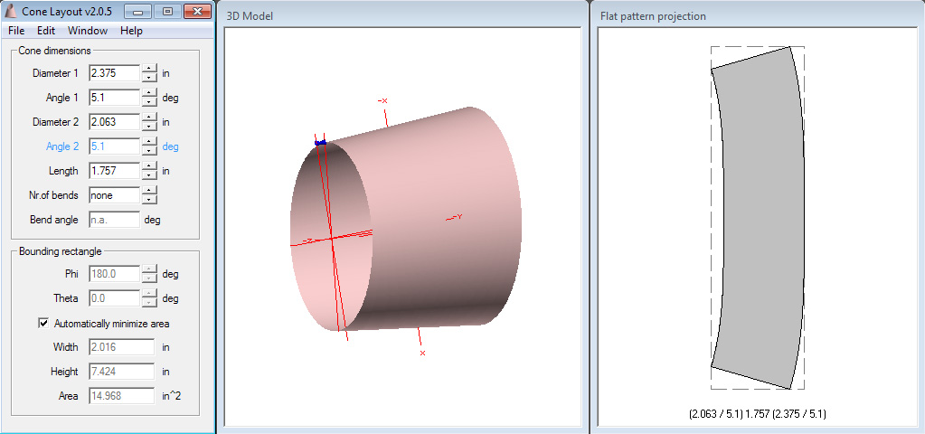
As you can see, the sides of the template are parallel and relatively flat in the middle, with more pronounced curves towards the ends. The flatter part is the bottom of the boiler course, where it is perpendicular to the ends. If we were to cut this out and roll it, it would give us the shape we want, where the bottom is perpendicular to the ends and the top has a distinct slope, but the seam is on the top. Ideally we want the seam on the bottom where it’s not so noticeable on the model. First, deselect the “Automatically minimize area” checkbox, then go back and change the angle of the faces from 5.10 to -5.10 (the tool rounds it to two decimal places). The template is now inverted so that the ends of the template are the bottom, and the middle is the top.
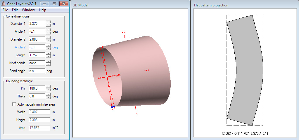
Now all we need to do is print out the template, trace it onto our material, cut it out and roll it. For my project, that’s going to be brass, but that’s a subject for another article.
